Transistor gate inverter logic not gates circuit diagram gif ttl digital used Simple "not gate" scheme Gate not circuit diagram electrical4u principle working ic
Xor gate
Not gate: how does it work? (circuit diagram & working principle Not gate circuit diagram and working explanation Circuit led gate not eevblog forum power
Gate fritzing
What is a not gate?Not gate circuit diagram and working explanation Logic inputWhat is not gate inverter, not logic gate inverter circuit using transistor.
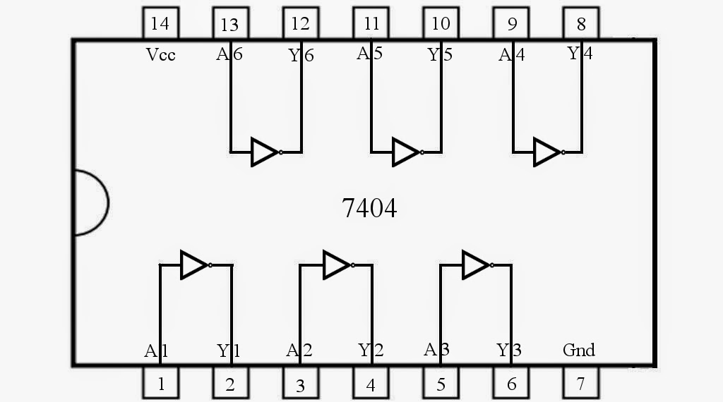
Rgb led circuitDiagram cmos gate 4049 circuit ic clip vector logic input svg hex datasheet pinout clker buffer integrated using large Gate not circuit diagram input power through button circuitdiagram explanation connected thenControl 7404, not gate ic, using arduino mega « funny electronics.

Xor nand nor transistor inverter complex
Gate not 7404 circuit ic diagram gates used vcc input using output led arduino part make ground electronics funny timerGate not circuit switching switch open logic symbol lamp when will illustrates glow go off figure Gate not circuit transistor logic inverter using truth tableXor gate.
Transistor logic not gateNot gate circuit diagram and working explanation Circuit diagram and gateGate ic not circuit 74ls04 pinout logic diagram xnor gates input working chip nor hex circuitdigest electronic electrical engineering diagrams.


circuit diagram and gate

What is a NOT Gate? - Logic Symbol & Truth Table - Circuit Globe

NOT Gate Circuit Diagram and Working Explanation

NOT Gate: How Does it Work? (Circuit Diagram & Working Principle

NOT Gate Circuit Diagram and Working Explanation
RGB LED circuit - Page 1

Control 7404, NOT Gate IC, Using Arduino Mega « Funny Electronics

Simple "Not Gate" Scheme

Transistor Logic NOT Gate - Inverter

Xor gate
